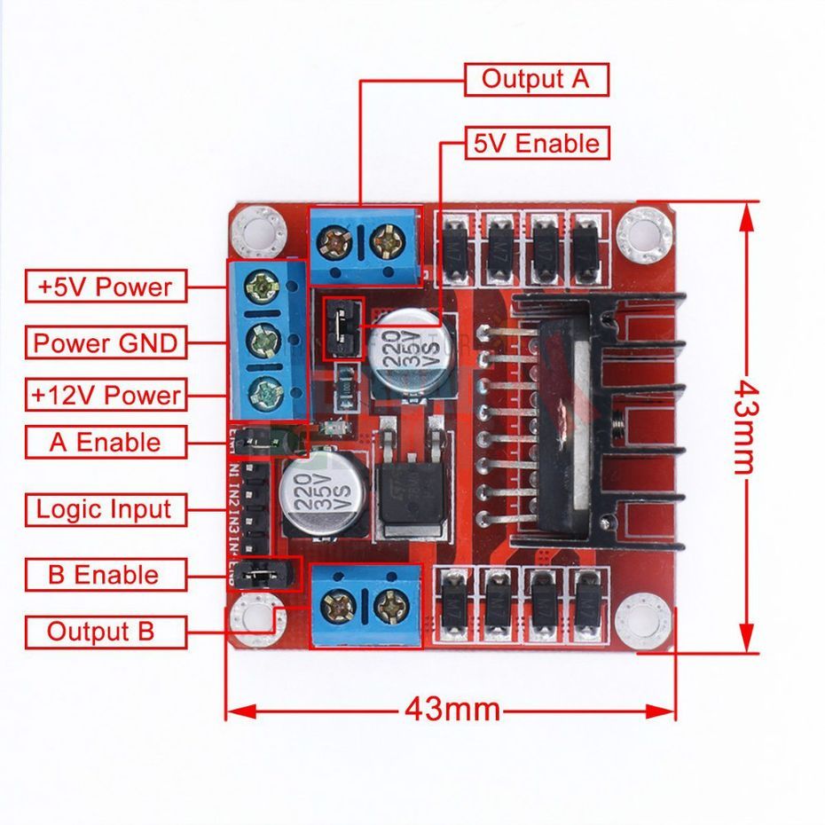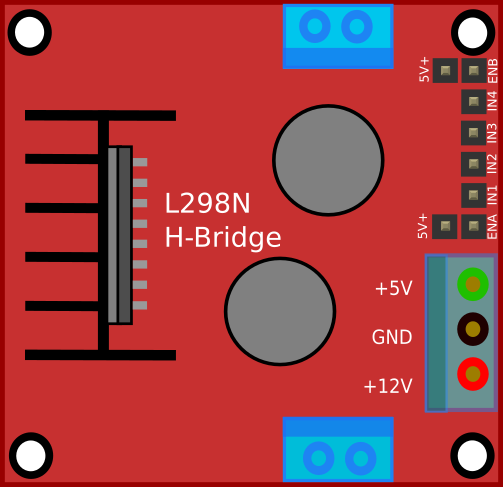
To drive both the motors by using H bridges, both enable bits are set high. While using as a bridge circuit, ENA selects bridge A and ENB selects bridge B. ENA can select two amplifiers A1, A2 and similarly ENB can select two amplifiers B1, B2. Enable bits are used to select specific amplifier.Instead of push button, we can use logic toggle in proteus simulation for our ease. We can use push buttons and whenever specific push button is pressed, specific motor will start running.

INPUTS: Four inputs are provided to the four power amplifiers of L298N.What we want to do is to change the polarity of motors so they can run in either direction depending upon logic. We will use H bridge motor diver IC L298N and two DCmotors. ENB=0v, Low logic (Amplifier B1 and B2 off).ENB=5v, High logic (Amplifier B1 and B2 on).ENA=0v, Low logic (Amplifier A1 and A2 off).ENA=5v, High logic (Amplifier A1 and A2 on).Both enable pins can be used at the same time which makes all for outputs active at the same time.All the four inputs and Enable pins work on 5v TTL logic which makes the connection easy with microcontrollers. Current sense pins can be tied to ground but we can also insert low value resistor and its voltage reading is proportional to current. They can be 1N5819 schottky diodes or 1N4001 rectifier diodes.Įach bridge is provided with enable pins (ENA, ENB) and current sense pins (CSA, CSB).

To avoid that voltage spikes there should be some internal parasitic or Flywheel diodes. Pair of H Bridge is used to control a bi-polar stepper motor.īasically L298N is used to drive inductive or magnetic loads, so there can come voltage spikes in output. One H bridge is used to switch the polarity in controlling direction of DC motor.

Two of them form H-bridge A while other two form H-bridge B. See FAQ:Where can I find “specific part” for information about looking for existing part files, and information needed to create new parts.L298N consists of four independent power amplifiers. Either as is, or as a base for something else. I would not try to use that downloaded part with out some serious cleanup first. To figure out where things are supposed to be, and what should be connected together. To do this properly, a datasheet for the part is really needed. What I see does not have labels except on breadboard, and the part validation tool I use has many complaints. Jumper wires (or cable) would run from the board to a header on the pcb instead. Really, this board does not normally need a pcb view.

Spacing and position of the pins on the pcb view also look off. I do not see any of that in the part definition though. Like multiple gnd, or +5V connecting to other +5. Wires are not connecting where they are dragged to except in breadboard view.įewer pins in schematic “CAN” be normal, in cases where multiple physical pins are connected together inside the part. My initial testing of a fresh download of that part says it is broken.


 0 kommentar(er)
